Shredder Line PSX-5240
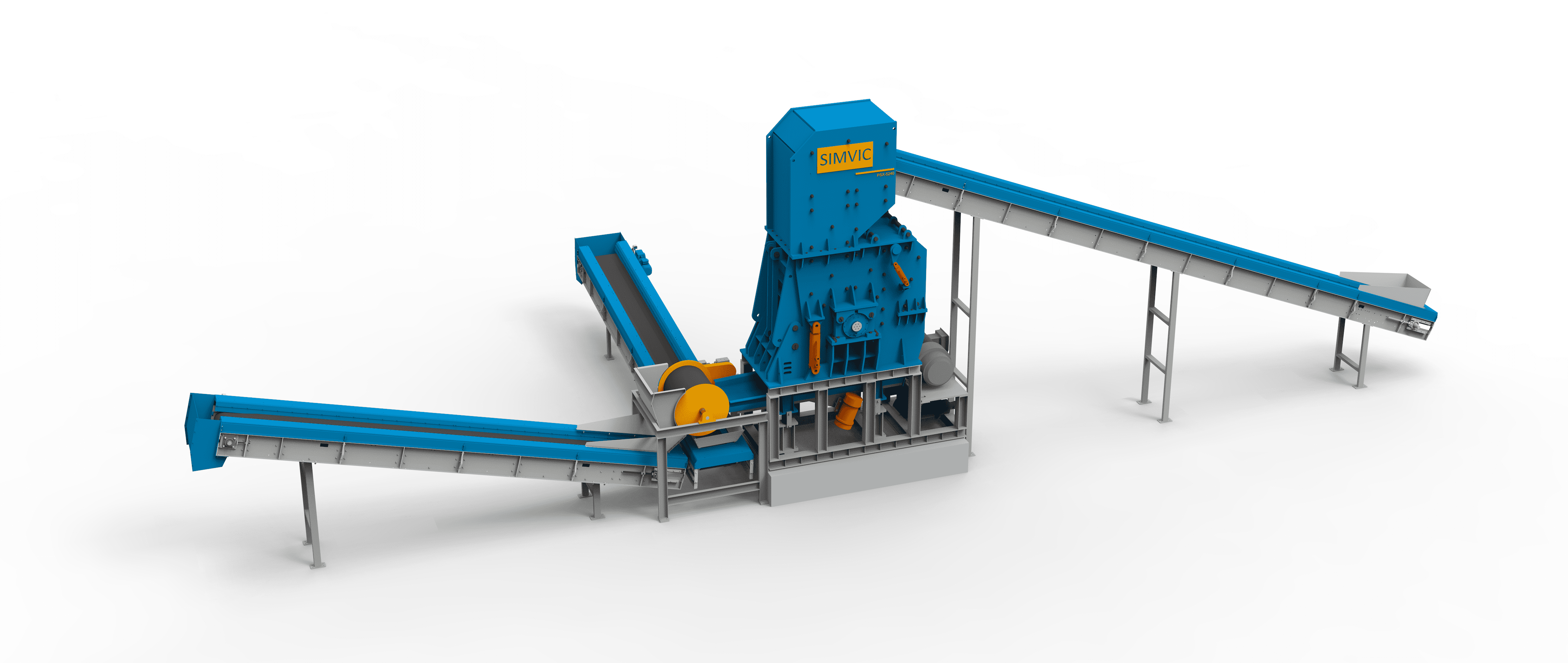
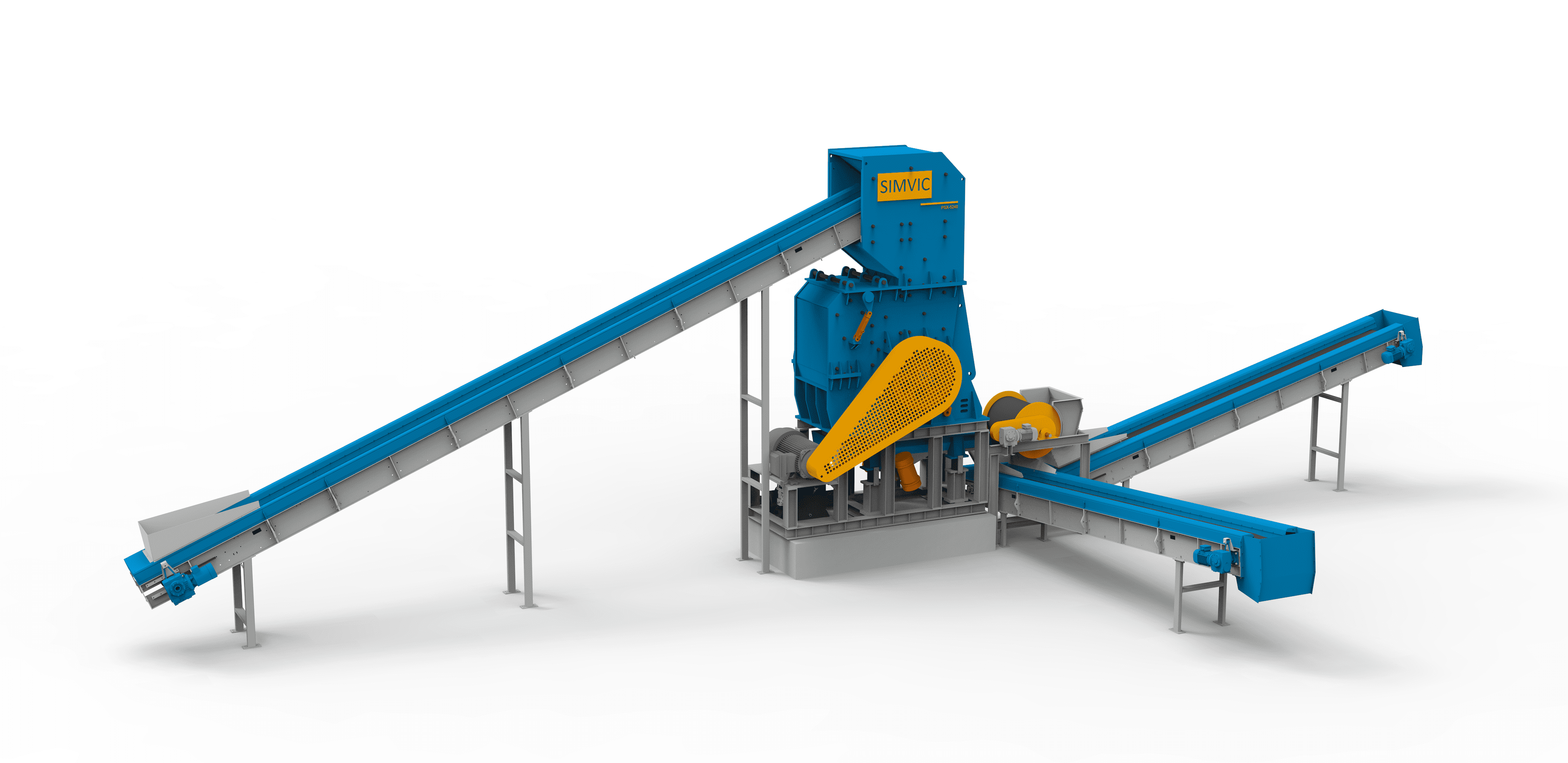
1. Main Technical data
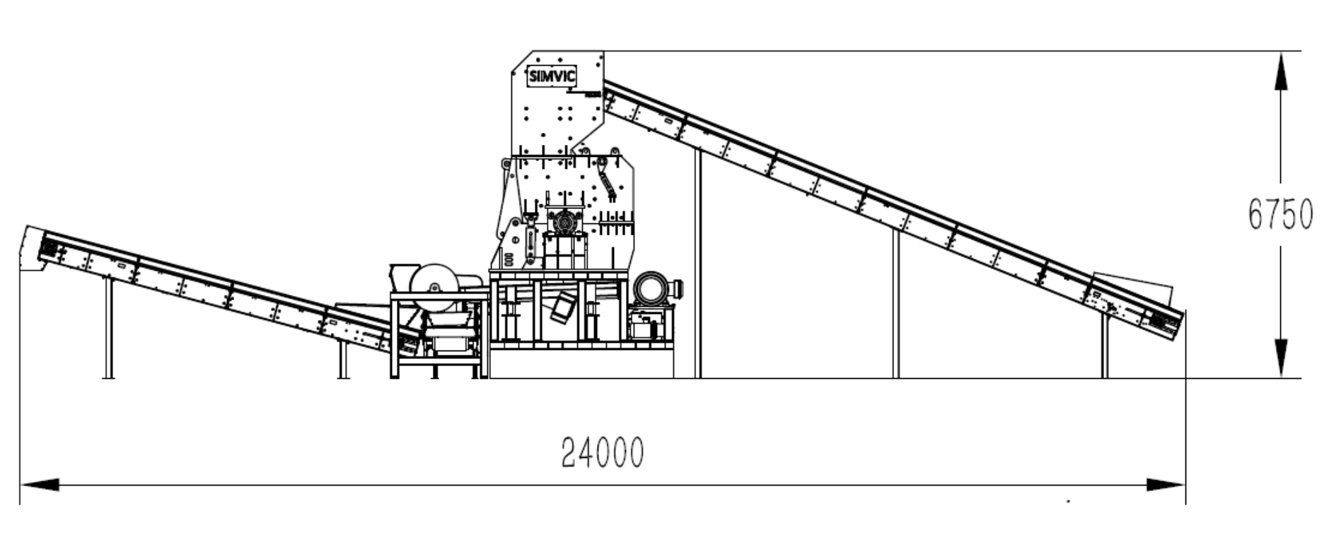
- Feeding Conveyor
- Shredder(Hammer Mill) 5240 ROTOR
- Main motor and controlling cabinet
- Vibration Feeder
- Drum Magnet
- Ferrous conveyor
- Non Ferrous conveyor
- Hydraulic Station
- PLC&Electrical Control system
2. Technical Description of Equipment
2.1 Feeding Conveyor
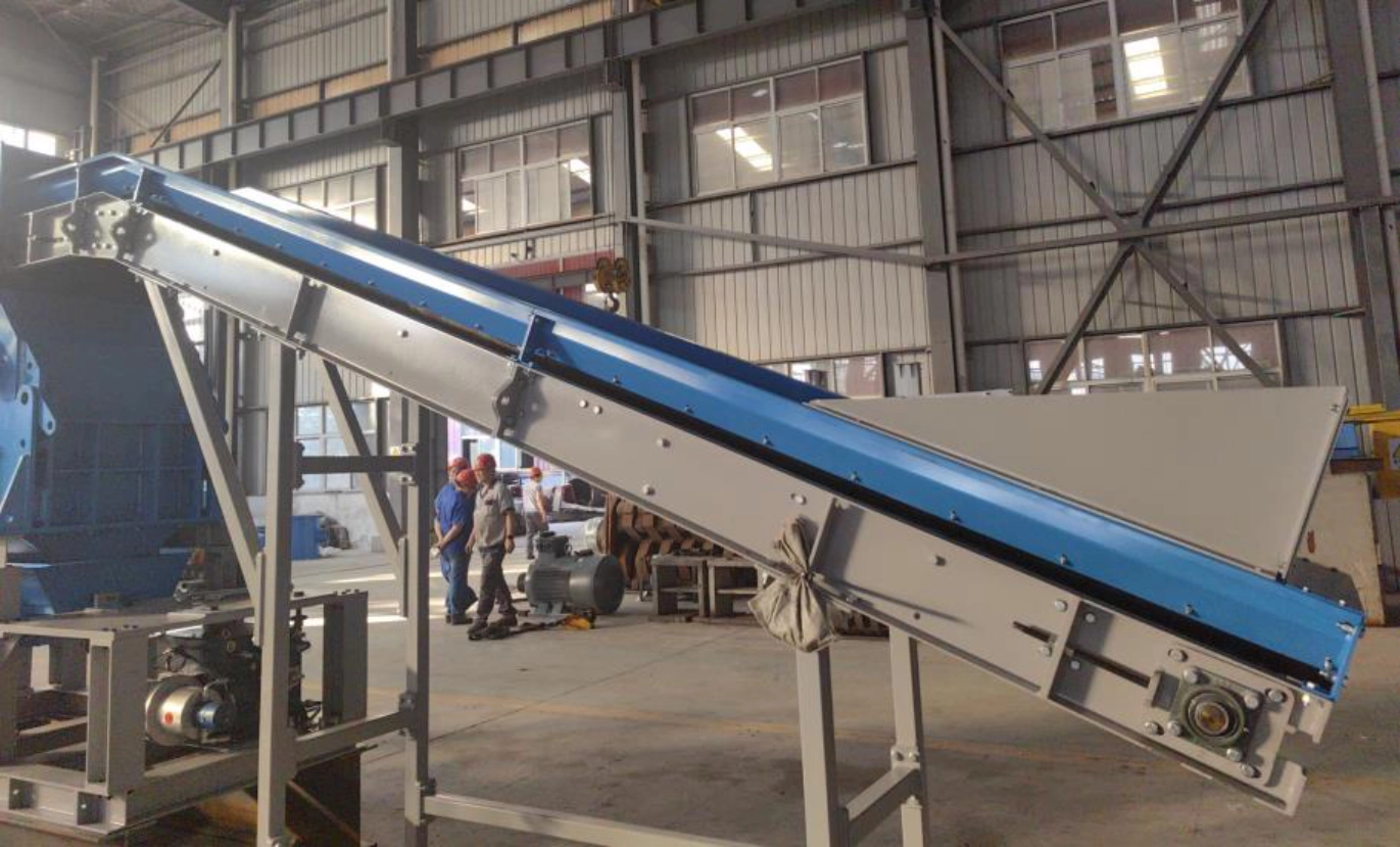
- Total Length: 5m
- Feeding Width: 400mm
- Feeding Angle: 22°
- Motor Power: 1.5kw
2.2 Shredder (Hammer Mill)
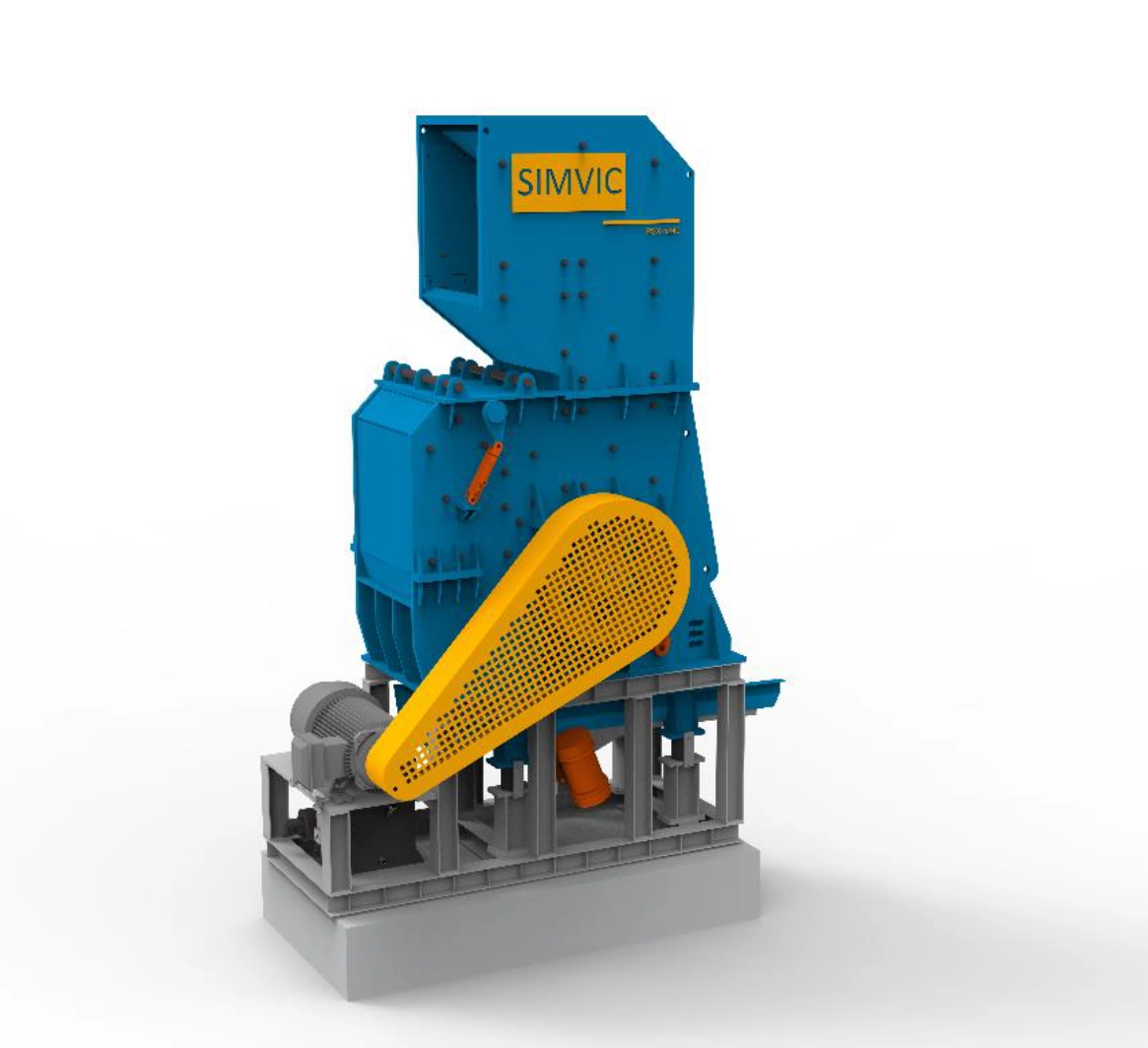
- Shredder weight: 35tons
- Case open cylinder: 760KN
2.2 a) Bottom, middle and feeding box
It consists of the base of the main machine, the middle part, feed box and rotor groups, hammer, liners. Under the beating of the hammer, it can get required scrap by tearing action after the material entering the scrap shredder.
The lateral and front parts of the main machine is welded with steel plate, the high manganese steel line is mounted inside. The super thick line is mounted on the bottom and the front, which protect the whole inner cavity of scrap shredder. When the scrap reaches the required size, it will be discharged from the bottom and front gate immediately, and the compressing stops. If the size is not small, it will be moved to the front and processed again until it can enter through the bottom or the top grid.
2.2 b) Discs Rotor
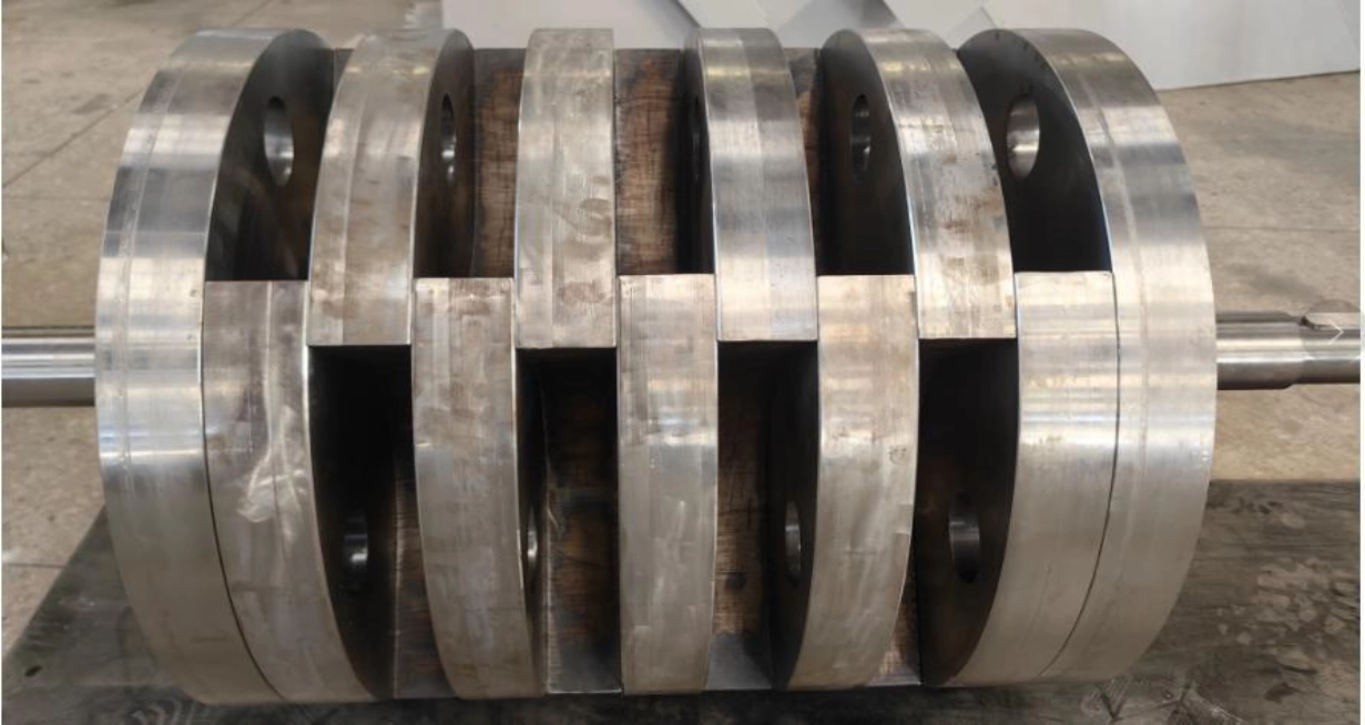
The rotor mainly consists of 9 center discs and 2 end discs manufactured in alloyed steel and a center shaft manufactured in thermally treated alloyed steel.
The rotor is equipped with 4 hammer pins manufactured in thermally treated alloyed steel and 10 iron hammers. The contact surfaces between the rotor discs and the hammer pins are protected by hardened and tempered protection caps. Every space between discs that does not contain a hammer is protected by hammer pin protectors.
- Number of hammers: 10
- Hammer rotation diameter: 1320mm
- Hammer pins: 4
2.3 Main motor and controlling cabinet
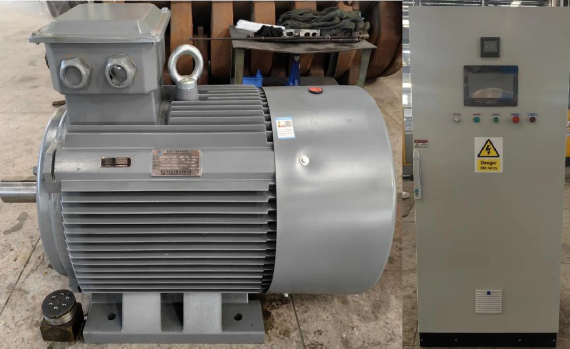
The main motor is the input source of power of the scrap shredder. It is wound rotor three-phase asynchronous motor. The rated working voltage is 6000v or 400V (to be confirmed by buyer), the rated frequency is 50Hz. The rated power is (PSX-5240). The synchronous speed is 595r/min. The temperature element is installed in the bearing of the high voltage motor, and removing moist device is included.
The high-voltage motor can control the starting, ending and running, and it includes protecting function such as short circuit, overload, phase failure, over-temperature and under voltage.
- Rated power of motor: 250KW
- Synchronous speed of high-voltage motor: 595r/min
2.4 Vibration Feeder
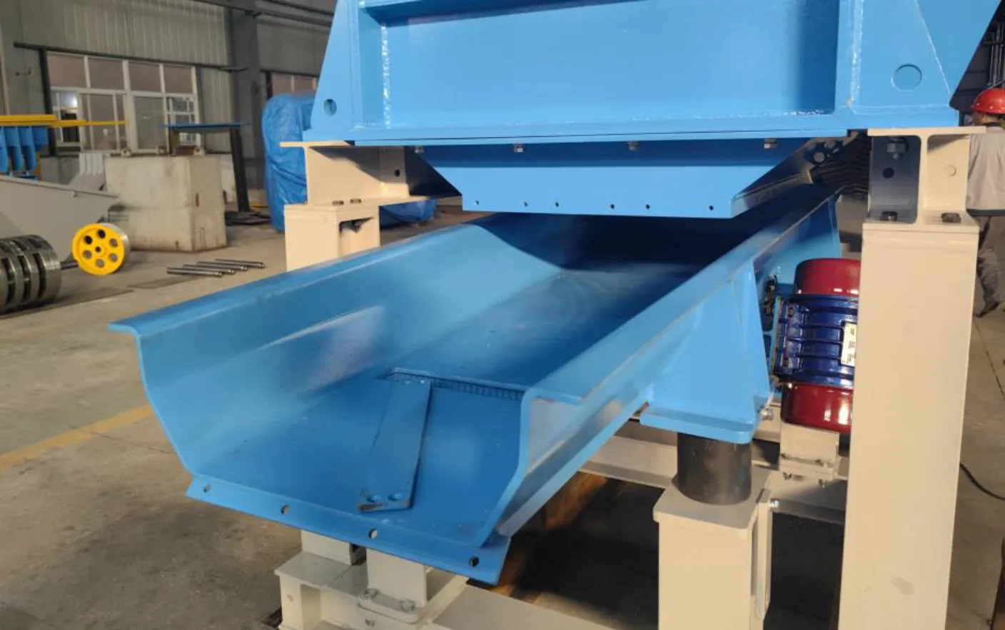
It consists of screen box, oscillating motor, eccentricity block, oscillation system and under frame. The oscillation system is driven by two same type oscillating motors, which make the screen box supported on the vibrator to vibrate linearly. The scrap is transported from the feed side to the discharging gate along the screen box to loose and separate the waste at the same time.
- Feed chute length: 3300mm
- Feed chute width: 1000mm
- Vibration motor power: 2x3.7kW
- Vibration amplitude: 4~5mm
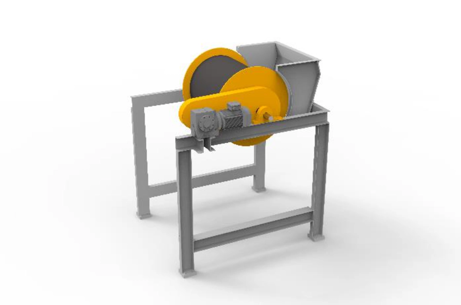
2.5 Drum Magnet
The suspended magnetic separator is installed at the exit of vibration table. It adsorbs iron metal from the passing materials.
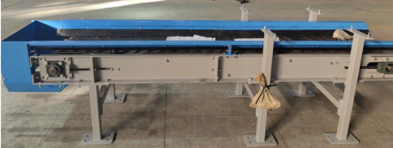
2.6 Ferrous Conveyor and 7 Non-ferrous Conveyor
The conveyor transfers the materials to the bunker.
2.7 Hydraulic Station
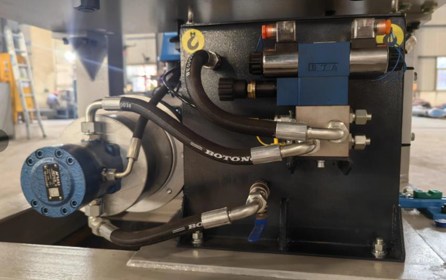
The hydraulic station is composed of an oil pump, an oil tank, a hydraulic valve, a valve, an oil motor, a filter, etc. The hydraulic station provides hydraulic energy for the flip cylinder. The oil is provided by the oil pump and is controlled through the control valve block and hydraulic valve to enable the cylinder to complete the corresponding functions.
- Pump: 25L/min
- Oil tank: 100L
- Pressure: 25MPa
- Motor Power: 11K
2.8 PLC & Electrical Control System
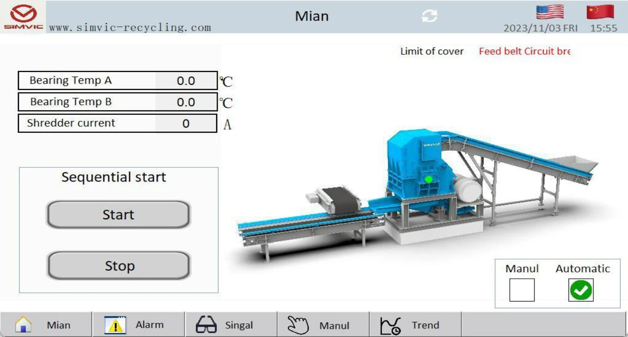
It considers high and low voltage motor, power distribution and electric controlling system of the whole line equipment. The main motor in voltage section is high-voltage:6KV/low-voltage:400V, 250KW. It completes the start, stop and run controlling by the high voltage control cabinet.
3. Work conditions
3.1 The lowest temperature for the equipment is -10℃
3.2 The electric and hydraulic rooms should install measures of cold protection and dust-proof. The window of the control room should have measure of bulletproof window.
3.3 If the temperature is above 5℃, the L-HM32 or L-HM46 hydraulic oil can be used. If below 5℃, it is suggested to use L-HV32 or L-HV46 hydraulic oil.
3.4 Power load (voltage and frequency to be confirmed by buyer) Power source: three-phase 380V 50Hz/60Hz
4. General conditions
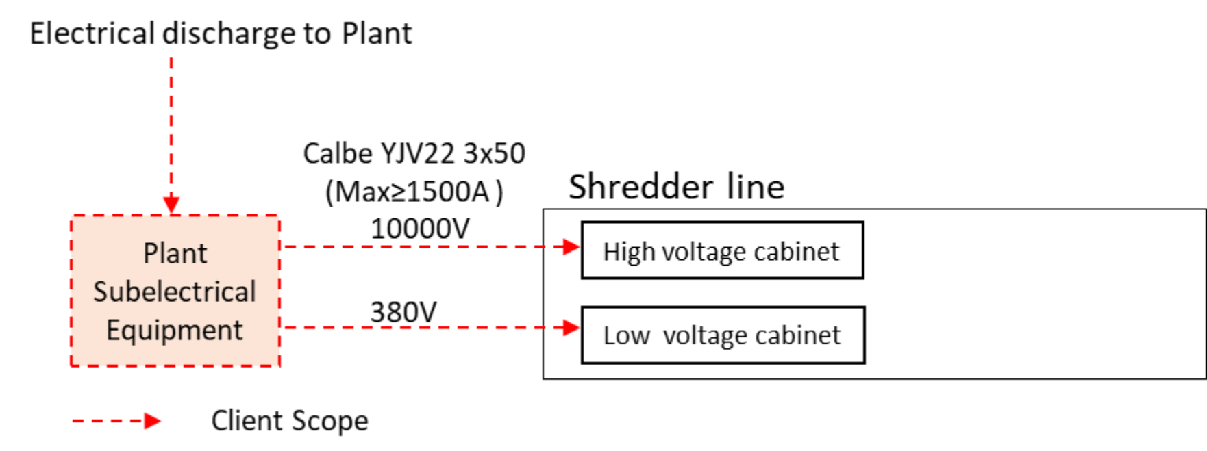
- Customer must ensure that a proper electrical discharge to ground is connected to the shredding plant.
- SIMVIC RECYCLING would provide the customer with an operation and maintenance manual with equipment delivery.
- Hydraulic oil is not included.
- The guarantee will be of 12 months from the starting up or 2000 hours of work and never higher than 18 months from the notice date informing goods are prepared to be picked up or transported(whichever is earlier) against manufacturing and assembling faults, except those produced due to natural wear and bad use or maintenance.
- To be valid the guarantee, the original spare parts will be bought to the manufacturer.
- Guarantee would be terminated if it were checked that spare parts not provided by SIMVIC RECYCLING have been used during guarantee period.
- If the starting-up of the installation was made without SIMVIC RECYCLING authorization and without SV from SIMVIC RECYCLING, SIMVIC RECYCLING would not be responsible of wrong operation of the installation.
5. Client Scope
- Electric works
- Equipment base design and construction
- Equipment assembly and installation
- Engineer from SIMVIC RECYCLING local accommodation
- Hydraulic oil
- Crain or lifting equipment for installation


